Current sensing Bay-O-Net fuse link
General
Eaton protects both distribution
apparatus from
damaging
currents and distribution
systems from
failed apparatus with its Cooper Power series
current sensing Bay-O-Net fuse link that is used
in Eaton’s Cooper Power series Bay-O-Net fuse
assemblies (see Catalog CA132015EN Sidewall-
Mounted and Cover-Mounted Bay-O-Net Fuse
Assembly). They are used on single-phase conventional
and self-protected distribution transformers
and other apparatus rated through 500 kVA, and on
three-phase equipment
through 1500 kVA.
A Bay-O-Net fuse is ideal for use in a two-fuse
protection scheme with a current-limiting backup
fuse. In this arrangement, secondary faults and
overload currents are cleared by the Bay-O-Net
fuse, and high level faults are cleared by the
current-limiting fuse. The two fuses are connected
in series, and are coordinated so that the
current-limiting fuse operates only upon internal
equipment failure. (See Catalog CA132013EN ELSP
Current-Limiting Backup Fuse to order an ELSP
current-limiting backup fuse.) If the Bay-O-Net fuse
will not be used in series with a current-limiting
fuse, an isolation link is required. (See Catalog
CA132012EN Isolation Link.)
Bay-O-Net fuses are comparable
in cost to internal
cartridge fuses but have the advantages
of being
field-replaceable. Bay-O-Net fuses can easily be
coordinated
with upstream devices.
INSTALLATION
No special tools are required. A hotstick is used
to remove the Bay-O-Net fuse cartridge holder
from non-pressurized apparatus. The fuse cartridge
is then replaced, and the holder reinserted
using a hotstick. Refer to Service Information
MN132002EN Bay-O-Net Fuse Re-fusing
Installation Instructions for re-fusing instructions.
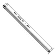
Figure 1. Fuse Link features and dimensional information.
NNot e: Dimensions given are for reference only.
SILVER-PLATED BRASS
CONTACTS
Provide reliable positive
current interchange.
0.365″ – 0.382″ Dia.
(9.3 mm – 9.7 mm)
CORROSION-RESISTANT
ELEMENT
Provides reliable fuse operation.
TEFLON® TUBE
Provides track-free bore to withstand
full-rated voltage after fuse
operation.
* Add suffix “B” to order individual fuse; add “M” to order bag of 50.
Table 2. Bay-O-Net Fuse Link
Continuous
Current
Rating (A)
Catalog
Number*
6 4000353C04
10 4000353C06
15 4000353C08
25 4000353C10
40 4000353C12
65 4000353C14
100 4000353C16
140 4000353C17
3.86″ – 3.90 ”
(98 mm – 99 mm)
Table 1. Electrical Ratings and Characteristics
Voltage
(kV) Catalog Number
Maximum Single-Phase Interrupting Rating*
Cover-Mounted Assembly
(rms symmetrical)
in Mineral Oil
Sidewall-Mounted Assembly
(rms symmetrical)
in Mineral Oil
Sidewall-Mounted Assembly
(rms symmetrical) in
Envirotemp™ FR3™ Fluid
8.3
353C04-C08 3500 A 3500 A 3500 A
353C10-C12 3500 A 3500 A 2500 A
353C14-C17 3500 A 3500 A 3500 A
15.5
353C04-C08 2500 A 2500 A 2500 A
353C10-C12 2500 A 2500 A 1500 A
353C14-C17 2500 A 2500 A 2500 A
23.0 353C04-C17 1000 A 1000 A 1000 A
* In Eaton’s Cooper Power series Bay-O-Net assemblies only. Where available fault current exceeds rated value, coordinated current-limiting fusing such as an ELSP (Catalog CA132013EN) or approved
equivalent must be provided.
Ordering information
To order a current sensing Bay-O-Net fuse link, determine the
requirements of the application from Tables 3 and 4 and specify the
fuse required from Table 2.
2
Catalog Data CA132009EN
Effective February 2015
Current sensing Bay-O-Net fuse link
www.cooperpower.

